MIL-DTL-15098E
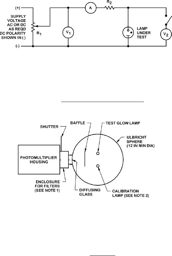
R1 - Resistance divider.
V1 - Voltmeter.
A - Ammeter impedance less than 1 percent of series impedance R2. For AC measurements, use a
thermocouple ammeter or equivalent.
R2 - Series resistor magnitude as specified for lamp under test (see 3.1).
V2 - Voltmeter minimum 10 megohms input resistance.
FIGURE 1. Design voltage and current test circuit.
NOTES:
1. For testing neon and argon indicator lamps, the filter shall be such that the frequency response of the
photomultiplier tube, photometer, or photo cell used in conjunction with a Kopp 5970 filter, or
equivalent, gives a narrow band response peaked at 360 nanometers.
2. Calibrate for light output at 3-month intervals, or less, using calibration lamps versus primary standard
lamps. Sources for primary standard lamps and calibration services are available through the National
Institute of Standards and Technology (NIST).
FIGURE 2. Test fixture.
13
For Parts Inquires call Parts Hangar, Inc (727) 493-0744
© Copyright 2015 Integrated Publishing, Inc.
A Service Disabled Veteran Owned Small Business